Geo-Connections Is Now Part of Dandelion

Tuesday, March 6, 2018

We are proud to announce that the tools that we have built over the past decade will now be offered through Dandelion, and we will be working hard to add to this toolset over the coming months.

Geo-Connections and Dandelion have been working together on some software projects over the past year. As we’ve worked together, it’s become clear to everyone involved that we are uniquely aligned in purpose and that we’ve been independently working to solve many of the same problems. To achieve what Geo-Connections has always sought — the widespread adoption of geothermal — we decided that we would be most effective officially joining forces with Dandelion.

It has been a pleasure and a privilege to serve you as Geo-Connections and we look forward to continuing our relationship with you as part of Dandelion. We are excited to continue building toward a world where geothermal is the go-to HVAC system.

Check out the full press release.

PACE + Geothermal

Wednesday, November 22, 2017

Ryan Green of Midwest Machinery Denver shares an overview of what PACE financing is and why it works so well for financing geothermal installations.

Duration: ~19 minutes

About the Presenter

Ryan Green
Midwest Machinery Denver

Ryan Green has over 6 years of experience in the energy efficiency and renewable energy sector, specializing in HVAC system retrofits, building energy use analysis and GeoExchange heat pump systems.

Ryan’s passion and drive for energy efficiency began only a few months after entering the HVAC industry. After witnessing the inefficiencies that exist and the potential for retrofits in aging infrastructure, his priority immediately shifted to curbing these inefficiencies. As a sales engineer for Midwest Machinery Denver, he works with consulting engineers, installing contractors, and end-users to provide cost effective and high efficiency HVAC system solutions.

Before relocating to work with Midwest Machinery Denver, Ryan was extremely active in many of the El Paso sustainability and advocacy groups and was a board member of the El Paso Chapter of American Society of Heating Refrigerating and Air Conditioning Engineers (ASHRAE), the United States Green Building Council (USGBC) West Texas Chapter Regional Committee, and Eco El Paso’s Sustainable Energy Committee.

Ryan has a mechanical engineering background and plans to finish his B.S. degree program at the University of Colorado Boulder. He is also training to become an accredited Certified GeoExchange Designer through the course offered by HeatSpring. He resides in Lakewood, CO with his wife and 2-year old son and likes to spend time reconnecting with nature when he’s not out trying to save it.

LoopLink GSE Update

Monday, November 20, 2017

Our geothermal savings estimation API, LoopLink GSE, recently received an update to improve accuracy and performance. We will start with what got better then talk a little about technical changes that will impact customer implementations.

More Accurate Utility Rates

In version 1 of the GSE API, we took statewide average utility rates and applied them to any search which didn’t include custom rates. In this update, we now search (in the US only) for local electric rates and apply those to the estimate. So, if your customer searches their home address we can typically identify the correct electric utility provider and rate.

We have yet to find a house level rate lookup tool for natural gas, fuel oil or propane. So those energy prices are still a statewide or regional average depending on data availability.

We know it isn’t optimal but due to the difficulty in finding consistent information for all countries, searches outside the US will resolve to the US national average for a given energy type. As demand increases in other countries we will look to improving our defaults. For now, know that if you intend to support other countries your best results will come from asking the homeowner for utility pricing.

Know the Place?

A place object has been added to the response which enables you to identify the location we found for the estimate. At first blush this doesn’t seem that valuable. After all, the user provided the location to initiate the request. The value is that now you have a way to provide feedback to the user to ensure that the place we found was in fact the place they searched.

Technical Note: We moved geocoding attribution data into this object… it just made logical sense to tie the attribution to the result.

Updated Load Model

We are always looking at our load model and working to provide more accurate results with the limited information we require from homeowners. In this update we did more work on tweaking our advanced parameters to account for duct placement, seal and insulation in a more accurate way.

Better Security and Accounting

Version 1 was a little naive in its implementation of Cross Origin Request Sharing (CORS). We have bolstered this method and improved our ability to identify sites that are registered to make requests as well as improved the accuracy of our per site request counts. This will greatly simplify your ability to make requests against our system and allow us to provide you with more accurate usage statistics.

Logging and Retrieval

We noticed that an awful lot of homeowners come back and enter the exact same information into the system multiple times. Rather than rerun these requests we have implemented a logging function that will store requests for up to one month.

We provide a unique estimate ID with each response that can be requested directly. So, now you can get a homeowner’s email and send them a link back to their estimated savings or send a local dealer a copy of the link with the homeowner estimate.

We do not accept or store contact information so it is up to your team to fill in those blanks.

GET or POST

In LoopLink GSE 1.0 we required all requests to be sent as a POST. This is no longer the case. You may now submit your data with a GET or POST. All other request methods are restricted.

Change Your Request Structure

In our first iteration we tried to build GSE to be as permissive as possible. We allowed users to just send us a location field that contained anything from a complete address to just a postal code. The tool worked but the search was buggy and while it always returned a result, the result may have been for the wrong place entirely.

To deal with this issue, we now ask for structured requests so we can more efficiently and precisely search locations. So what was previously sent to us as:

  • location=1234 Any Street, My Town, SD 12345 USA

Is now sent as:

  • street = 1234 Any Street
  • city = My Town
  • state = SD
  • postal_code = 12345
  • country = USA

You don’t necessarily need to send us every piece of information but we we now require that you include the country in a search based strictly on postal code.

Search Coordinates Directly

In the ideal interface, your user will run a location search in the browser through Google Maps or a service like Zillow (which provides some square footage information). Which means there isn’t a good reason for us to geocode the location on our end. You can send us coordinates directly which does speed up many of our results. Just remember that any search containing ‘lat’ and ‘lon’ fields will be reverse geocoded to establish rates and other location information.

In the update, you no longer need to provide the ‘geocoded’ flag. We automatically detect the 'lat' and 'lon' fields and handle the request accordingly.

3 Ways Geothermal Design Software Improves Your Sales Pitch

Friday, November 17, 2017

Experienced geothermal contractors know the importance of building value with their prospective customers. While that value can be demonstrated in many ways, contractors should not overlook the importance of using geothermal design software to help them win the job. When you sell geothermal comfort systems, you need to show your prospects that they can make a seamless transition to the new system and that its higher cost will pay off in the long run.

Geothermal design software can do just that. Homeowners considering a geothermal system to replace an aging HVAC system want it to be easy. Your prospective customers know just enough about the technology to expect a higher level of “engineering” than in a standard HVAC system. They need confirmation that you designed and sized the job correctly without overcharging.

Using geothermal design software can demonstrate to your customers that you’re the expert and that they can trust you to simplify their transition to geothermal heating and cooling. Here are three reasons why.

1 Using Geothermal Design Software Demonstrates and Confirms You Chose the Right Unit

“Old school” or “rules-of-thumb” sizing techniques commonly employed by those without geothermal design software are problematic.

Oversizing a geothermal unit is much more expensive than oversizing a gas furnace. Doing so could price you out of a job.

Undersizing the unit will require excessive backup heat, eliminating energy savings. Your customer doesn’t want the auxiliary heat activated when it’s 35 degrees outside. Sizing a smaller unit than competitors may get you the job, but the homeowner won’t be satisfied with the purchase if energy savings are lacking. That might cost you a referral.

2Using Geothermal Design Software Demonstrates and Confirms You Sized the Loop Correctly

Rules-of-thumb don’t work for sizing loops, either.

Overestimating the loop size raises the price for the homeowner while underestimating it may cause excessive loop temperatures, reducing capacity and efficiency. Excessive loop temperatures may cause unit lock-outs and require emergency heat in the winter, or failure to cool during the summer.

Many geothermal dealers rely on loop contractors to size and build the loop. This can be risky. Even if you sub-contract the loop installation, use geothermal design software for sizing the unit and the loopfield. At the end of the day, it is the HVAC installer not the loop contractor holding the bag if a system fails.

3 Using Geothermal Design Software Demonstrates and Confirms Long Term Value

Homeowners invest in a geothermal system to save money on their utility bills. Geothermal design software demonstrates that savings with head-to-head comparisons of various options for that customer’s home. With local fuel rates and estimated efficiencies, geothermal software will be make running simple payback and 30-year saving analysis quick and easy.


About the Author

Kent Kuffner
Carrier Corp.

Kent Kuffner is the Residential Geothermal Heat Pump Product Manager for Carrier, Bryant and ICP brands. He has been in the geothermal heat pump industry since 1989 in various roles in manufacturing and distribution, and authored the geothermal heat pump chapter in the HVAC Handbook, published in 2004 by McGraw Hill. He is a member of IGSHPA and currently serves as the Chairman of the Marketing Committee.

Geothermal Can Change The World

Friday, October 6, 2017

Geothermal heating and cooling systems are sold to homeowners and building owners with a focus on how their system will improve their lives. The direct benefits and individual case is a critical part of making the sale but its not the only set of benefits you should present.

Don't forget that many consumers interested in geothermal are often just as interested in the big picture truth that geothermal can change the world. Every GSHP system improves our energy future and here are some numbers to help you back that up.

Pure Energy

The United States uses nearly 25% of the world’s energy but only represents about 5% of the world’s population. At the residential level, more than 70% of home energy use is for space conditioning and hot water generation.

A 2010 study from Oak Ridge National laboratories found that if we could convert every single family home in the U.S. to using geothermal for heating, cooling and hot water generation, it would save 4.2 Quadrillion Btus annually (4,200,000,000,000,000 Btu for those who need to see the full number...that’s a lot of commas). This is based on reducing the consumption of all forms of energy for space conditioning and hot water heating (natural gas, propane, oil, electricity, etc.).

That amount of energy is equivalent to 1.2 trillion kWh (1,230,898,494,723 kWh). For perspective, the total residential sales of electricity in the U.S. amounted to 1.4 trillion kWh in 2015. Not a bad start to reducing energy consumption.

Less Gassy

Even compared to homes using electricity for heating/cooling, geothermal emits less upstream greenhouse gases simply because it consumes less energy. Check out the estimated difference below.

Home Heating Fuel GHG Emissions (per Therm)1
Electricity 27 lb
Oil 17 lb
Propane 14 lb
Natural Gas 12.5 lb
GSHP 7 lb
11 therm = 100,000 Btu (Source Dandelion)

According to the EPA, the average house is responsible for twice as many greenhouse gas emissions as the average car. Based just on the pure energy savings GSHPs clearly translate to a massive reduction in greenhouse gases (GHG).

How big?

Oak Ridge National laboratories puts the estimated CO2 reduction at 271.7 million metric tons annually. According to EPA estimates that is equivalent to taking 58 million cars off the road.

What About The Benjamins?

Oak Ridge estimates that at 100% adoption for single family homes, homeowners could save as much as $52.2 Billion dollars per year with geothermal. That is a stack of one hundred dollar bills 35 miles tall. That is A LOT of Benjamins.

Tell Everyone!

If the world really wants to take a bite out of greenhouse gases and get a handle on global energy consumption, geothermal heating and cooling brings us a long way towards that reality. Solar, wind and every other green technology that is kicking the pants off of geothermal in sales falls far short of the impact that can be realized with geothermal alone.

More importantly, geothermal supports all of the other renewable energy technologies. Solar and wind proponents should be screaming from their rooftops for the world to adopt geothermal. Because geothermal automatically drops off the peak summer demand by at least 30% which means a larger percentage of the national baseload can be generated by renewables.

Depending on who you ask, the estimated geothermal market share currently hovers around 1-2%. Imagine if we could bump that to 5% by replacing half of the propane and oil furnaces in the U.S. It would save the homeowners money, save an astronomical amount of energy and reduce GHG significantly more than those same homeowners buying electric cars.

Geothermal is the right technology to reshape our energy future. It’s a shame we have to bury it.

Geothermal Equals Peace of Mind

Monday, October 2, 2017

There are many benefits of ground source heat pump systems (GSHP). They are energy efficient and environmentally friendly. They provide comfort levels that are unmatched by conventional technologies. They are an in-home luxury that can be used for both spacing conditioning and domestic hot water generation.

GSHPs also provide price stability and financial peace mind. Month to month, GSHP heating bills are as reliable and predictable as the systems themselves.

Heating Bill? Well it Depends on the Price.

With a geothermal heat pump system, the amount of energy used to heat and cool a home can be cut by anywhere from 40% to 70%. As great as that sounds, the savings offered by a GSHP may not be enough to offset the upfront cost to install such a system in somes cases.

First cost relative to savings (typically referred to as simple payback) isn’t the only thing to consider. A prospective client should be aware of the fact that fossil fuel prices tend to jump around A LOT more than electricity.

Consider the following graph which shows the historical cost to deliver 100,000 Btu of heat energy to a home (based on the national average for energy prices by year since 2001).

Cost per 100,000 Btu by Heating Fuel and Year1


GSHP Operating Costs are Predictable

The cost to deliver 100,000 Btu with a GSHP has been steady since 2001, even though the average price for electricity has increased by over 40% over that time period. This just reiterates the fact that GSHPs act as a safeguard against inflationary energy prices.

The interesting thing to note is how much the cost to deliver the same amount of heat energy with competing fossil fuels has bounced around over the same time frame. Consider the following table which highlights the year with the highest average price (by fuel type) and the range of monthly average prices within that year:

Price Range by Fuel Type During Peak Year1

Fuel Gas Propane Oil GSHP
Worst Year 2008 2014 2013 2014
Average Cost $1.63 $3.53 $3.55 $0.81
Range $1.42 - $2.43 $2.92 - $4.95 $3.44 - $3.68 $0.78 - $0.86

Budget for the Winter

Assuming an average 2,500 ft2 home in Brookings, SD, this is what the heating bills could look like in January and through the entire heating season given the variability in energy prices during the worst year:

January Heating Bill in Brookings, SD1

Fuel Gas Propane Oil GSHP
Year 2008 2014 2013 2014
January Bill $210 - $360 $435 - $730 $510 - $545 $115 - $130
Annual Bill $1090 - $1860 $2240 - $3790 $2630 - $2820 $600 - $660

Given the amount of variability in price for fossil fuels, homeowners that rely on them for heat really have no way to predict how big their next heating bill might be. Life is full of surprises. The heating bill doesn’t need to be one of them.

Footnotes

  1. Prices based on national averages, EIA

Luxury Comfort Systems

Wednesday, September 27, 2017

Compare your sales strategy to that of a car dealership. Other HVAC salesmen are shilling an old pickup with poor gas mileage. You're offering a luxury sports car that happens to get better mileage than anything else on the road. Geothermal is the most advanced AND energy-efficient HVAC system on the market - it has a higher price-tag for good reason (“The Masterpiece of HVAC Technology”).

From Bragging Rights to Public Relations

Homeowners have a budget for nice things. They want them first, and they want other people to know they have them.

Corporations have the same philosophy, and they have an even larger audience to impress. Of course, they want bragging rights among their peers. But they also want to impress the public. Proving that they've "gone green" with geothermal will make their public relations director’s job easy.

Quality is another high priority for either type of customer. Customers don't want to replace their heating systems. They want a system that will last for a long time. Studies have shown consumers believe that quality products aren't cheap.

Your potential customer will pay more for bragging rights and for the best product available. Geothermal offers those bragging rights and it is the best HVAC product available. You just have to prove it.

How Do You Prove It?

Geothermal is state-of-the-art. It's environmentally-friendly. It has a cool factor. Instead of wasting precious fossil fuels, you're using solar energy stored in the earth's crust to heat your home! Include these qualities in your sales pitch.

Unlike solar panels, windmills, or Tesla badges geothermal is an “invisible” green technology. You have to explain the benefits instead of showing them. Provide customers with a list of features proving that they'll be the greenest neighbor in the hood - or business park - when they purchase a geothermal system.

Tell your customers that geothermal heat will allow them to:

  • Remove excessive outdoor equipment, opening up valuable real estate
  • Avoid replacement costs associated with traditional HVAC systems (underground geothermal pipes are not susceptible to outside elements)
  • Eliminate traditional HVAC noise pollution (fans and compressors outside)
  • Eliminate fresh water consumption (from cooling towers; typically on commercial HVAC systems)
  • Eliminate on-site greenhouse gas (GHG) emissions by replacing the boiler/furnace
  • Be the coolest neighbor in the hood (using the earth's crust to heat your house)

Start with these qualities and slowly work your way down to less-exciting aspects. Don't start your sales pitch with interminable flow charts and cliche-riddled speeches about how the investment will pay off over X number of years. Be bold. Tell your customers that your product is more expensive because it is better.

Public Validation

Find an expert to further validate the technology you’re selling. Let’s say you want to build a house. You’re looking for a design expert. An architect would probably be your best bet, right?

Well, architects happen to be outspoken about their love for geothermal. They love the peaceful, quiet ambiance, and the elimination of outdoor condensers and cooling towers. These articles in Commercial Architecture and Green Builder Media will help you illustrate these points clearly. Is there a better spokesperson than someone who designs buildings?

Government officials are also hopping on the bandwagon. Your customers should know that geothermal heat may eventually be required. Things are trending this way in the U.S. and abroad:

  • Ontario’s building code will eliminate combustion heating in new homes by 2030
  • Enbridge (North America’s largest natural gas utility) is switching from gas lines to geothermal loops in new developments
  • The state of New York has earmarked billions of dollars for reducing GHG emissions
  • Google spin-off, Dandelion has entered the market

Your Sales Pitch Summary

Geothermal heat is garnering worldwide praise, with advanced technology that justifies its high price. There is your sales pitch.

About the Author

Jay Egg
Egg Geothermal

Jay is a consultant and designer of geothermal HVAC systems, in addition to being author of two books and several articles on the subject. He is the Founder of Egg Systems, and focuses on geothermal consulting, engineering, and contracting technologies.

Jay Egg started Egg Systems in 1990 to provide energy efficient geothermal air conditioning systems to the Florida, and especially the Tampa Bay markets. Jay Conducted his first speech in 1994. Afterwards, Tampa Electric Company (TECO) began to rely on Mr. Egg’s training expertise utilizing him in various forums from conventions to in house educating. Jay co-authored with Brian Howard for McGraw-Hill a professional book on the subject of Geothermal HVAC, Green Heating and Cooling, published in 2010. He also co-authored with Greg Cunniff and Carl Orio a graduate – level textbook for McGraw–Hill, Modern Geothermal HVAC Engineering and Controls Applications which got published in July, 2013. Jay is a featured writer and speaker, most recently having been selected as featured speaker for The Renewable Energy World Conference & Expo North America 2011.

Water Quality in GSHP Applications

Wednesday, June 21, 2017

Water quality has a huge impact on GSHP service life and efficiency. Unfortunately, most systems are filled with whatever water is available on site with little or no attention to its suitability for use.

In fact, water quality is the root of many issues, including the premature failure of mechanical components. It goes without saying that if you aren’t already paying attention to water quality, it’s time to start.

Water treatment can be divided into two categories: physical and chemical. Physical water treatment consists of the removal of air, dirt and suspended solids from the circulating fluid. Chemical treatment consists of the modification or elimination of substances in the water to make it suitable for contact with the various components in the system.

1 Physical Water Treatment

Every geothermal system will start out with air in it. A new system will also have certain amounts of dirt, oil, pipe shavings, and other debris as a byproduct of manufacturing, transport, and installation.

The majority of air removal is done with power flushing prior to system startup. Dirt removal is done simultaneously with a filter during power flushing1. Geo-Flo recommends filtration to 100 microns during the flushing and purging process. Once air is purged from the system, a finer 1-micron filter will remove sand, silt, and clay from the circulating fluid.

After system startup, additional air and dirt removal is possible with the right mechanical devices:

  • Air removal: high-point vents or central air separators
  • Dirt removal: filters, strainers and particle separators

Failure to remove air and debris from the piping system will cause service-related issues and even shorten the service life of the circulating pumps and other related components. Permanently-installed mechanical devices can provide ongoing levels of physical water treatment, but keep in mind that they will need to be cleaned periodically.

2 Chemical Water Treatment

Although air and dirt removal is essential, physical treatment doesn’t affect water chemistry.

Water is commonly referred to as the ‘universal solvent’. It is always full of dissolved minerals, sediment, dissolved gasses, etc., and the amounts vary from place to place. If left unchecked, poor water chemistry can lead to corrosion, scale, fouling and biological growth, which affects system efficiency and service life and becomes a human health and safety concern. Treatment may include the removal of chemical impurities, pH value adjustment, or the addition of antifreeze, corrosion inhibitors, microbial control products, etc.

There are many different ways to approach water chemistry. Here are a few that are common in GSHP applications:

Internal Cleaning
The process of cleaning an internal piping system is fairly straightforward. Simply circulate a cleaning solution (detergent) through the piping to remove dirt, oils and other impurities. After the process is complete, the system will need to be completely drained and washed with clean water prior to being filled with loop fluid.

By removing impurities from the system on the front end, it will be easier to achieve the desired level of water quality later on. Note that internal cleaning is uncommon in residential applications.

On-Site Water Treatment
One option to address water chemistry is to simply add inhibitors to prevent corrosion, scale, biological growth, etc. The inhibitor manufacturer will provide guidelines to determine proper concentration levels, handling and safety requirements, etc.

For heating dominant systems that use antifreeze, additional inhibitor is typically unnecessary as most antifreeze products are are pre-mixed with the necessary inhibition agents.

Transport
Rather than adding chemicals to available water on-site, another option is to purchase treated water (or a premixed water-antifreeze solution) from a water or chemical treatment company, haul it to the jobsite and completely replace the water in the system with the pre-treated fluid. This is the easiest way to guarantee that water quality will not be an issue, but also the most expensive.

Measures of Water Quality

In general, it is best to refer to the manufacturer of each component in the system to determine water quality requirements (pH level, dissolved solids, turbidity, chloride levels, etc.). If guidelines aren’t readily available, Section 3B in IGSHPAs Design and Installation Standards manual will serve as a great starting point.

The most relevant measure of water quality is dissolved mineral content.2 In general, the use of de-mineralized fill water will alleviate the majority of issues related to scale and corrosion.

Remember to Check In

The circulating fluid should be tested periodically to check pH, turbidity, suspended solids, antifreeze and inhibitor levels, etc. IGSHPA recommends that water quality be checked at least once a year in a commercial system and once every five years in a residential system.

By comparison, GSHP systems are more forgiving than other HVAC system types when it comes to water quality, primarily because most of the piping in the system is the ground loop, which is constructed of inert plastic (polyethylene). But poor water quality will wreak havoc on pumps, heat exchangers, valves, and other mechanical devices in the system. As such, water chemistry always needs to be addressed.

Footnotes:

  1. According to ASHRAE, 2 ft/sec is the recommended velocity to remove air and light debris from a piping system. However, this velocity is not enough to remove large or heavy particles and additional filtration is recommended.
  2. Refer to Idronics #18 for additional information.

Flow Centers: Pressurized vs Non-Pressurized (Part 2)

Monday, June 19, 2017

As described in the first part of this article, flow centers require a certain minimum level of inlet pressure in order for the pumps to function properly. The method of maintaining this pressure is what distinguishes a pressurized flow center from non-pressurized flow center.

In some cases, the choice of which type of flow center to use is based on application constraints. But most of the time, the decision is based on preference. When faced with the decision, consider the pro’s and con’s of each type of system.

Pressurized Flow Centers

Advantages

  • No monitoring and/or maintenance required by the homeowner
  • Smaller size reduces space needed for installation
  • Completely closed and sealed design prevents air and debris from entering the system after installation
  • Typically packaged to include three-way isolation/flush valves
  • Flexible location and orientation installation options
  • Can be installed vertically or horizontally (12-, 3-, 6-, and 9-o’clock positions)
  • Can be plumbed in series or parallel
  • Provides single point isolation location between the ground loop and heat pump
  • Very familiar to plumbers and hydronic technicians

Disadvantages

  • No built-in provision for air elimination
  • Thermal expansion and contraction of loop piping along with insufficient startup pressure may lead to a flat loop1
  • Poor installation practices that result in leaks can cause pumps to air lock, flat loop service calls, etc.
  • Requires a qualified technician for maintenance (fluid levels, antifreeze concentration, etc.)
  • Requires flushing, purging and re-pressurization after servicing

Non-Pressurized Flow Centers

Advantages

  • Water column provides inlet pressure
  • Allows direct measurement of fluid levels, flow rate, and antifreeze concentration, even during operation
  • Fluid reservoir facilitates natural air removal and accommodates loop expansion and contraction
  • Homeowner can perform basic maintenance (such as adding make-up fluid)
  • More forgiving of poor installation practices (incomplete flushing, small leaks in piping, etc.)
  • Pump service does not require the system to be re-flushed
  • With the right manifold, may be able to flush and purge the loopfield without an external flush cart2

Disadvantages

  • May promote poor installation practices due to forgiving nature
  • Direct access to loop fluid opens possibility for contamination
  • Requires more space for installation
  • Limited installation locations and orientations3
  • May require additional field-installed isolation valves for flushing/purging, servicing, etc.
  • Individual flow centers cannot be installed in series or parallel

So, Which Flow Center Is Better?

All differences aside, both types of flow centers will perform well when installed properly. Each has its own advantages and disadvantages to consider. In the end, it is up to the installation contractor, system designer or building owner to decide which system best meets their needs.

Footnotes:

  1. The installation of an expansion tank is recommended to alleviate the concern of a flat loop.
  2. Requires an inside building header with isolation valves placed on each individual loop.
  3. Piping must not be located more than 30 feet (approx.) above the reservoir, which can only be installed vertically.

About the Author

Jeff Hammond
Geo-Flo Products Corp.

Mr. Hammond is currently Director of Business Development and Marketing at Geo-Flo Products Corporation, a manufacturer of flow centers and accessories for the geothermal heat pump and hydronics industries. He started with the company in 2012, and has been in the geothermal heat pump industry for over 30 years.

Previous to Geo-Flo, he was at Enertech Global for five years, ClimateMaster for nine years and WaterFurnace International for twelve years. Mr. Hammond’s experience in the industry consists of positions in R & D, engineering, product management, training, sales, and marketing. His education includes a bachelor of business administration from the University of St. Francis and an associate of applied science in electrical engineering technology from Purdue University.

Mr. Hammond has been a member of ASHRAE since 1990 and has served on CSA, AHRI , and IGSHPA marketing, technical and advisory committees.

5 Ways to Extend Pump Life for GSHP Systems

Monday, June 12, 2017

According to ASHRAE research, GSHP units have a service life expectancy of more than 24 years. At 10 years, the average service life of a wet rotor circulator pales in comparison.

Geo-Flo recently conducted a review of the warranty claims they received due to pump failures. The data suggest that the majority of premature pump failures are due to preventable issues.

Pump Failures at a Glance

The chart shows the breakdown of warranty claims in the analysis by Geo-Flo.

As illustrated, only 10% of failures were due to mechanical issues. The majority of failures were due to preventable problems. Poor water quality accounted for half of the failed pumps and improper installation practices contributed another 10%.

Fortunately, the solutions to the majority of pump failures are inexpensive and very easy to implement. Here are the top five:

1 Filter the Loop Fluid

The simplest thing to do is to use a filter when flushing the system prior to startup. Particulate matter such as fine sand or clay can build up in the small passageways and can even erode internal pump components.

Typically, a 100-micron filter during flushing is sufficient to remove pipe shavings and other debris that may have been introduced during installation. Keep in mind that silt and clay particles can be smaller than 75 microns. Once air is purged from the system, a finer 1-micron filter should be used to reduce the potential for sand, silt, and clay to eventually end up in the circulating pump.

2 Properly Address Water Quality

Although filtering is essential, it doesn’t address bad water chemistry. Water quality is the most critical factor in how a pump performs over the life of the system.

While bronze or stainless steel volutes will stand up to poor water quality better than cast-iron, they don’t solve the real problem. With a simple volute substitution, the pumps will last longer but the rest of the system (including the heat exchanger in the GSHP) is still exposed to bad chemistry and could fail instead.

Municipal water systems and well water may not have proper water chemistry and can be detrimental to system longevity. In some cases, it may be best to transport treated water or a pre-mixed water and antifreeze solution to the jobsite.

3 Avoid Air-Lock

Wet rotor circulators are cooled and lubricated by the fluid flowing through them. An air locked pump will eventually overheat and fail. To avoid air-lock:

  • Take care to properly flush and purge the system prior to startup (remember that filter).
  • Include an expansion tank or fluid reservoir above the pump suction with a pressurized flow center.
  • Include pressure and vacuum relief components with a non-pressurized flow center.

4 Keep Electrical Connections Dry

In general, electricity and water don’t mix. The terminal box needs to be located so that condensate from the ground loop piping can’t drip onto the electrical connections.

Also, cold loop temperatures may create the potential for condensate to form inside the pump itself. If the pump housing floods, water will contact the electric connections and create a short. This is why circulators used in GSHP applications include condensate drain holes.

Circulators that do not have condensate holes (such as those used in boiler applications) are not suitable for geothermal applications.

4 Use Coated Motor Windings

Coated motor windings are recommended to extend pump life, especially in cold climates where condensation is a concern. They protect against damage due to moisture, corrosion, vibration, etc. Generally, a pump with coated windings will be more durable.

5 Check for Proper Pump Orientation

Water flow through a pump needs to be in the vertical plane, which requires the pump shaft to be horizontal. Similar to an air-locked pump, a vertically-installed pump shaft can lead to eventual failure caused by the top bearing running dry without cooling or lubrication.

When in doubt, refer to the pump installation manual provided by the manufacturer, which will address the majority of these issues. Use these tips while following manufacturer guidelines to extend pump service life, lower overall life cycle costs and increase customer satisfaction.

About the Author

Jeff Hammond
Geo-Flo Products Corp.

Mr. Hammond is currently Director of Business Development and Marketing at Geo-Flo Products Corporation, a manufacturer of flow centers and accessories for the geothermal heat pump and hydronics industries. He started with the company in 2012, and has been in the geothermal heat pump industry for over 30 years.

Previous to Geo-Flo, he was at Enertech Global for five years, ClimateMaster for nine years and WaterFurnace International for twelve years. Mr. Hammond’s experience in the industry consists of positions in R & D, engineering, product management, training, sales, and marketing. His education includes a bachelor of business administration from the University of St. Francis and an associate of applied science in electrical engineering technology from Purdue University.

Mr. Hammond has been a member of ASHRAE since 1990 and has served on CSA, AHRI , and IGSHPA marketing, technical and advisory committees.

Pros and Cons of Distributed Pumping

Monday, June 5, 2017

Exceptional pumping system design is a giant step toward a high-performing geothermal heat pump system. Pump power consumption can drastically impact the overall efficiency of the GSHP system which ultimately affects the amount of heat rejection that the ground loop has to accommodate (which affects size and first cost).

There are many ways to approach pumping system layout and design, but they generally fall into one of two categories: centralized or distributed. As with anything else, the process of finding the best approach given your application starts with an evaluation of the the project.

Distributed Pumping Basics

A distributed pumping system typically uses a circulator per heat pump (or zone) to provide sufficient flow for that unit (or zone). In many cases, a separate (variable speed) pump will be used to produce flow through the loopfield in addition to the circulators for each unit in the building, as shown in the illustration.

While there is no limit to the size of the system that can be designed with a distributed pumping philosophy, this approach is best suited to unitary or sub-central systems where small circulators can be combined to meet system pressure/flow requirements1.

After comparing the installation and operating costs to the alternatives, it is also important to evaluate the maintenance requirements relative to personnel capabilities with a distributed system, which will generally be higher than a centralized solution.

The next step is to take a full accounting of the pros and cons of distributed pumping, a few of which are as follows:

Pros:

  • Piping design can mimic the simplicity of a residential / light commercial system, which is easier and less expensive to install.
  • Simple on-off control can be used.
  • Flow can be reduced all the way down to the needs of a single heat pump, whereas a central pump will have a lower operating limit (generally 20-25% of design).
  • If a single pump fails or is taken offline, the rest of the system will be unaffected and able to operate normally.
  • Net pumping energy and related operating costs are often the lowest with this approach2.

Cons:

  • Small pumps generally have lower overall efficiency values than larger pumps.
  • The number of possible failure points, as well as the number of pumps to maintain will be far greater compared to a centralized pumping solution.

Best Suited For:

Additional Notes:

  • The installation of check valves for backflow prevention when the units are off will be necessary at each heat pump.
  • Because of the relatively poor efficiency of small circulator pumps, it is critical to minimize friction losses in the piping system to maintain high system efficiency.

The best energy management strategy is to turn things off when you don’t need them. With distributed pumps, simple on-off control can be used which has been shown to drastically reduce pump energy use. But having a large number of pumps scattered throughout a building may not be conducive to staying within maintenance budgets or personnel capabilities.

If maintenance requirements are a concern, it may be worth looking at the Pros and Cons of Centralized Pumping to see if that strategy is a better fit for your system.

Footnotes:

  1. Refer to Chapter 6 in Geothermal Heating and Cooling: Design of Ground-Source Heat Pump Systems (Kavanaugh and Rafferty, 2014).
  2. A field study showed that on-off pump control strategies provide the highest ENERGY STAR ratings and that variable speed pumping systems do not perform as well as predicted. In the study, the average pump size was 6.6 hp per 100 tons for unitary on-off pumping systems whereas the average pump energy size was 13.5 hp per 100 tons for central variable speed pumping systems.

Flow Centers: Pressurized vs Non-Pressurized (Part 1)

Tuesday, May 30, 2017

In terms of residential flow centers, the geothermal heat pump industry is divided into two camps: pressurized and non-pressurized.

A flow center is a device that produces system flow and facilitates the removal of air and debris (through built in flush/purge ports)1. The terms “pressurized” and “non-pressurized” indicate whether static pressure is held in the piping system, which is measured when the circulating pumps are off.

Pumping Basics

Most of the pumps used in residential applications are wet rotor circulators. These pumps require that the inlet (suction side) pressure exceeds a certain minimum value, which is specified by the manufacturer (NPSHr). The amount of pressure available at the inlet (NPSHa) must be greater than the minimum for pumps to function properly. If the inlet pressure falls below the minimum, cavitation can become an issue.

There are two ways to maintain pressure at the pump inlet, which is where our conversation begins:

Pressurized Flow Centers (Static Pressure > 0 psi):
Static pressure is induced in the piping during start-up with an external source (i.e. a flush cart).

Non-pressurized Flow Centers (Static Pressure = 0 psi):
Suction-side pump pressure comes from the weight of a standing column of water (in a reservoir).

Both types of flow centers have been used with great success in the residential GSHP market. A brief history lesson may explain why both types exist in the first place.

The Early Days2

In the late 70s and early 80s, pressurized flow centers were the only option available. Most contractors installed standard hydronic components as part of the system (image courtesy of Waterfurnace International).

While these systems worked well initially, the condensation that formed during heating mode operation caused steel expansion tanks to rust and prematurely fail. Additionally, barbed and/or threaded connections were common, which tended to leak over time with the wide swing in ground loop temperatures (and pressures) from winter to summer.

The Shift to HDPE

In the late 1980s, the industry moved from polybutylene pipe to HDPE. Due to its thermal expansion capabilities, many industry practitioners concluded that an expansion tank was no longer needed, especially for residential and light commercial applications.

During this time, the “hydronic specialties” (expansion tank, air separator, etc.) were removed from most flow centers (image courtesy of Waterfurnace International).

Since HPDE pipe expands and contracts, it behaves like an expansion tank. However, it expands more quickly than the fluid, causing the static pressure in a system to drop in the summer. HDPE is also viscoelastic, meaning that it will stretch but not return to its original shape. Unfortunately, these characteristics led to loop pressures that fell below the minimum (NPSHr), causing what many referred to as a “flat loop”. Flat loops caused pump cavitation, GSHP lockout (due to low flow) and premature pump failure.

Making things worse, air bubbles still in the system after startup or maintenance tend to expand with decreasing pressure. The larger bubbles created noise, air-locked pumps and in extreme cases, they even blocked ground loop circuits.

Introducing Non-Pressurized Flow Centers

Being wet rotor circulators, most residential systems require very little suction pressure for proper operation (typically around 1 psi or less). The weight from a small column of water is all that is needed to maintain inlet pressure for this style of pump3.

Armed with this knowledge, frustrated contractors began adding reservoirs to alleviate issues caused by static pressure loss and HDPE thermal expansion/contraction. Following suit, flow center manufacturers began production of non-pressurized options in the 90s. The use of non-pressurized flow centers has grown steadily since then (image courtesy of Geo-Flo).

Today’s Choices

Since the introduction of non-pressurized flow centers, industry veterans have begun to revisit the use of hydronic specialties (expansion tanks, air separators, etc.) to minimize flat loop service calls with pressurized systems. This shift has led to a very high rate of success with both types of flow centers.

Since both work well, the contractor is left to choose the system that provides the best fit for the application. When choosing between the two, careful consideration of the pros and cons of each may help with the decision4.

Footnotes:

  1. ANSI/CSA C448.0-16, Design and installation of ground source heat pump systems for commercial and residential buildings
  2. Based upon the author’s experience in the industry since 1986.
  3. A 2.3 ft. column of water above the pump inlet provides the required NPSHr for proper operation (1 psi = 2.31 foot of head).
  4. This is the first in a two-part series. Part two of this article will cover the advantages and disadvantages of pressurized and non-pressurized flow centers.

About the Author

Jeff Hammond
Geo-Flo Products Corp.

Mr. Hammond is currently Director of Business Development and Marketing at Geo-Flo Products Corporation, a manufacturer of flow centers and accessories for the geothermal heat pump and hydronics industries. He started with the company in 2012, and has been in the geothermal heat pump industry for over 30 years.

Previous to Geo-Flo, he was at Enertech Global for five years, ClimateMaster for nine years and WaterFurnace International for twelve years. Mr. Hammond’s experience in the industry consists of positions in R & D, engineering, product management, training, sales, and marketing. His education includes a bachelor of business administration from the University of St. Francis and an associate of applied science in electrical engineering technology from Purdue University.

Mr. Hammond has been a member of ASHRAE since 1990 and has served on CSA, AHRI , and IGSHPA marketing, technical and advisory committees.

Pros and Cons of Centralized Pumping

Monday, May 22, 2017

With a ground source heat pump system (as with anything else), the designer must strike the right balance between installation and operating costs. This is true of all aspects of design, but is especially true of the interior piping design as well as the pump layout and selection. Even with the best design, the efficiency gains from a GSHP system can be completely erased by poor piping and pumping design (due to excessive head loss, oversized pumps, improper control, etc.).

While there are many options with respect to pumping system layout and design, they generally fall into one of two categories: centralized or distributed. While there are merits to both approaches, the process of finding the best choice for your application starts with an evaluation of the the project.

Centralized Pumping Basics

A centralized system will use one or more pumps at a central location to induce flow through the loopfield and then distribute it to the units scattered throughout the building, as shown in the illustration.

For large systems that fall in this category, variable speed control is common (and may even be required)1.

In general terms, the use of a centralized pump will be well-suited for a building with a small footprint where the interior piping can easily be connected to the GSHP units that are scattered throughout2. Centralized pumping may also be ideal for applications with significant load diversity where ‘load sharing’ principles can be used to reduce overall loopfield requirements3.

To determine whether this design approach is the best choice for your system, start by estimating the installation and operating costs and then comparing them to a distributed pumping approach. Next, take a full accounting of the pros and cons of centralized pumping, a few of which are as follows:

Pros:

  • Large pumps generally have better overall efficiency values than the smaller pumps used in distributed arrangements.
  • When required, maintenance is performed at the central pumping station (located in the mechanical room or dedicated pump house) which provides adequate access and minimal disturbance to the rest of the building.
  • Maintenance costs and personnel requirements are generally the lowest with this approach.

Cons:

  • A large interior piping loop must be used to connect all of the GSHP units to the central circulating pump, which requires proper design, increases complexity, requires the use of larger pipe sizes and drives up installation cost.
  • VFD flow control can be complicated and central systems must be balanced for proper operation4.
  • Failure or shutdown of the pumping system will cause the entire system to be down.

Best Suited For:

  • Buildings with small footprints and/or significant load diversity2.

Additional Notes:

  • To avoid system shutdown due to failure or routine maintenance, redundancy with a standby pump (in parallel with the main pump) is recommended. With redundant pumps, duty cycling is important to help with pump longevity and to even out service life expectancy.
  • When variable speed control is required, flow control measures (such as zone valves and pressure sensors) are necessary.
  • With variable speed control, the pressure drop in the distribution piping should be kept low. Additionally, the system should be balanced during startup to ensure proper control can be achieved.
  • Variable speed pumps should be designed to never operate below 25% of design flowrate to ensure that the motor and VFD efficiencies remain relatively high. For most GSHP systems, a large percentage of operating hours for the year will be at the lower end of the flowrate (idle or with 20% to 40% of GSHP units operating).

In a large GSHP system, a centralized pumping solution may be beneficial because of the low number of pumps required along with their central placement (which comes in handy when maintenance is required). But the system designer must select a pump that meets pressure and flow requirements while also providing economical operation, which can be tricky at part load conditions.

Because of the increased complexity of system design and control, as well as the lower limit on flow with variable speed equipment, it may be worth looking at the Pros and Cons of Distributed Pumping to see if it is a better fit for your application and more importantly, a better fit for your customer.

Footnotes:

  1. Per ASHRAE 90.1 (2016), “Hydronic heat pumps and water-cooled unitary air conditioners having a total pump system power exceeding 5 hp shall have controls and/or devices (such as variable-speed control) that will result in pump motor demand of no more than 30% of design wattage at 50% of design water flow.”
  2. Refer to Chapter 6 in Geothermal Heating and Cooling: Design of Ground-Source Heat Pump Systems (Kavanaugh and Rafferty, 2014).
  3. LoopLink PRO can be used determine how much ground loop reduction is possible with load sharing principles for a given system.
  4. A recent GSHP field study indicated that less than 10% of the ground-loop variable speed pumps with differential pressure transducer control were operating as intended due to faulty controls or had pumps large enough to provide near full-load flow rate at minimum motor speed (Kavanaugh 2012).

Geothermal Loops: 5 Reasons for using HDPE & PEXa

Tuesday, May 16, 2017


With so many available options, why has the geothermal heat pump industry gravitated toward exclusively using polyethylene (PE) - specifically HDPE and PEXa - for ground loop construction, especially considering it is one of the most insulative piping materials available?

Aside from the fact that PE piping accounts for a tiny fraction of the overall thermal resistance in a loopfield1, it offers a lot more benefits than deficits.

Photo courtesy of ISCO Industries.

Industry Standards

HDPE and PEXa are the only materials that IGSHPA formally approves for use in the buried portion of a closed-loop GSHP system. Per Section 1C of IGSHPA's Design and Installation Standards:

The acceptable pipe and fitting materials for the underground portion of the ground heat exchanger are high-density polyethylene (HDPE), as specified in Section 1C.2 and cross-linked polyethylene (PEXa), as specified in Section 1C.32.

These recommendations were born out of a combination of past experience along with the acknowledgement of the many advantages that polyethylene (PE) has to offer. Aside from being the industry standard, here are the top 5 reasons for using PE over the alternatives:

1 Affordable & Available

Polyethylene is used in a wide range of applications such as food packaging, plastic bottles and bags, pool liners, and of course, geothermal piping. It is a commodity plastic and is among the least expensive types to make. Geothermal grade polyethylene pipe is mass produced and readily available in the marketplace at commodity prices.

2 Durability

Geothermal heat pump systems operate under a wide range of temperatures and pressures. It is normal for ground loop temperatures to swing from 25-30F in heating mode to 90-100F in cooling mode. Thermal expansion and contraction of the piping due to temperature swings will cause system pressures to follow suit.

Polyethylene is highly resistant to damage due to fatigue (as well as damage due to abrasion, weathering, corrosion, etc.). It can withstand the abuse of pressure fluctuation due to temperature changes, as well as the abuse of being transported and handled on the jobsite. According to the Plastic Pipe Institute, it can even withstand damage due to an earthquake:

The toughness, ductility and flexibility of PE pipe combined with its other special properties, such as its leak-free fully restrained heat fused joints, make it well suited for installation in dynamic soil environments and in areas prone to earthquakes.

The durability of PE pipe is tough to beat (pun intended).

3 Installation Ease

Mechanical fittings are not necessary when PE pipe is used. Simple heat fusion techniques are used to join pipe and fittings together in a leak-free, virtually fail-proof manner. Even if leaks or other errors occur, they are extremely easy to fix.

PE pipe is also relatively flexible, lightweight and very easy to manage on the jobsite. Pipe coils are generally available for purchase in any 100-ft increment, leaving it to the installer to pick the length that best suits the project without the hassle of a special order.

4 Service Life

The life expectancy of polyethylene is greater than any mechanical component inside of the building, and even the building itself. According to Chapter 7 in the Handbook of PE Pipe:

The service life of HDPE pipe manufactured from today’s materials is expected to exceed 100 years.

In fact, most pipe manufacturers offer a 50-year warranty to guarantee that the pipe will perform according to specifications without failure of the material itself.

5 Maintenance Free

The long service life coupled with the use of heat fusion in lieu of mechanical fittings virtually eliminates the need for maintenance on the pipe itself. Once installed, the buried ground loop will be a permanent fixture on the property for as long as there is a building to heat and cool.

Polyethylene is also corrosion resistant and inert to most chemicals. It does not promote biological growth and helps to minimize the amount of water quality-related issues typically associated with a water-source HVAC system. Alternative piping materials such as steel, copper and galvanized iron are much more demanding from a maintenance point of view.

All things considered, HDPE and PEXa are far and away the most practical choice for geothermal loopfield construction.

Notes:

1GeoPro’s Importance of Grout TC illustrates the fact that pipe is a very small portion of the overall thermal resistance in a loopfield. In fact, LoopLink PRO can be used to show that the thermal resistance of a basic HDPE or PEXa u-bend accounts for only 10%-12% of the overall total.

2Refer to IGSHPA's Design and Installation Standards for further information on pipe manufacturing methods and materials, pressure ratings, dimensions, tolerances, etc.

Soil Identification for Horizontal Geo Loops

Tuesday, April 18, 2017

Soil identification can serve as one of the largest obstacles to generating an accurate horizontal loop design. That’s because it plays a large part in determining how many trenches are needed and how long they need to be. While it may sound simple, soil identification isn’t an area that most people are formally trained in.

Soil Properties

To design a horizontally-trenched loopfield, the important soil properties - thermal conductivity and thermal diffusivity - need to be quantified. These properties are dependent on three primary factors:

  • Soil type
  • Moisture content
  • Density

As described in this article, it is generally best to be conservative and assume that both density and moisture content are average to below average, unless you have enough information to justify a different assumption. Beyond that, soil type is the only factor left to define, which is where your homework begins.

Possible Resources

There are a number of resources to help determine soil type at the job site. County soil maps, soil survey reports and geotechnical reports may serve as a decent starting point in your search. Local excavation contractors that provide services such as septic tank installation may be able to provide firsthand knowledge of the soil type in an area as well.

Possibly the best, most accessible source of information is the USDA’s Web Soil Survey (WSS).

Using Web Soil Survey

WSS is a free online service that provides access to soil data collected by the National Cooperative Soil Survey, and is very easy to use. Soil identification is done in three simple steps:

  1. Enter the project location. WSS accepts many different forms of input for location - address, latitude and longitude, Public Land Survey System (PLSS) coordinates, etc.
  2. With the correct location shown on the map, simply zoom to the area where the loopfield is to be located and draw a box to create an Area of Interest (AOI).
  3. View soil type(s) in the AOI.

Once the AOI has been successfully created, WSS provides a free pdf download of the soil report, which includes:

  • Soil map with legend
  • Detailed description of the soil types along with the occurrence level for each (expressed as a percentage)

To download the report, simply click on the “Shopping Cart” tab, name the report, choose the options in Table of Contents, and click Check Out to begin the download process.

Try an Example

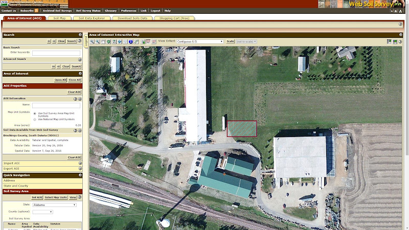
For example, our office is located at 302 E. Warehouse St., Elkton, SD 57026. Enter this in the search box, zoom in to create an AOI as shown:

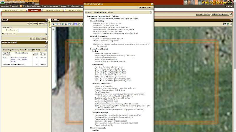
Once the AOI has been defined, the ‘Soil Map’ link will show a detailed map of the soil types in the area. For this example, the predominant soil type in the area is Silty Clay Loam (Z181A - Brandt)

Click here to download the sample report for this example.

Soil Identification in LoopLink RLC

Once you have identified the soil type in your area, assigning soil properties in LoopLink RLC is relatively easy:

  1. Assign soil density level (low, average, high)
  2. Assign soil moisture content (dry, typical, wet)
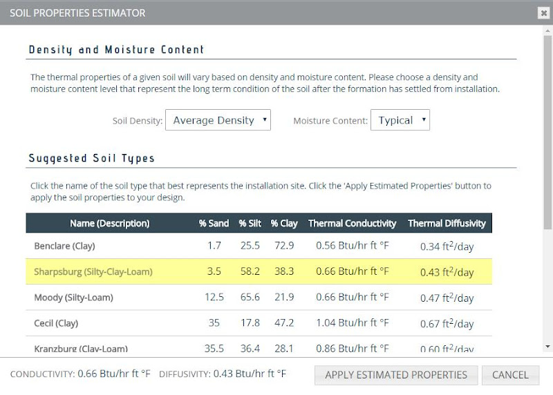
  3. Find a similar soil type in the Soil Estimator

In general, leave the selection for moisture content and density level at the default settings unless better information is available (i.e. a geotechnical report is available and provides enough detail to justify a change). From there, simply choose the soil type that most closely matches the soil identified in WSS. When making your choice, focus on the description in the table (clay, silty-loam, etc.).

Once you’ve made your selection, LoopLink RLC will provide recommendations for soil thermal conductivity and thermal diffusivity and you can proceed with the horizontally-trenched loop design.

Although soil identification can be intimidating (especially to the new designer), it is vital to accurate loop design. USDA’s Web Soil Survey breaks down this barrier. The service is easy to use and best of all, it’s free!

Top 4 Reasons Not to Use a Vault

Tuesday, March 7, 2017

A geothermal valve vault serves as a central point where the manifold collects flow from the entire loopfield with a single pair of supply-return lines running back to the building.

A well-designed vault has incorporated bypass and butterfly circuit isolation valves, which are used during system fill, flush & purge and pressure testing. These features are important and necessary, but you don't need to install a vault to include them in your design.

Here are the top four reasons to avoid using a geothermal valve vault in a commercial loopfield according to Howard Newton, Director of Geothermal Design at Image Engineering Group.

Photo courtesy of Image Engineering Group.

1 First Cost

As with any mechanical component, cost-benefit must always be considered. Whether pre-manufactured, or built on-site, The up-front cost for a geothermal valve vault can be significant.

If mechanical room space or distance from the building are non-factors, a detailed cost comparison like the one performed by Dr. Kavanaugh in ASHRAE's commercial geothermal design guide (Example 9.2 on page 353 - "To Vault or Not to Vault") to look at the loopfield investment with and without a vault.

2 Large Pipe Must Be Used

In order to accommodate the combined flow for the entire system, large diameter piping must be used.

  • Large diameter piping is expensive, and has much higher internal volume requirements, which results in the need for a large amount of antifreeze (when used)
  • Fusion equipment is larger, more expensive and unwieldy for the installer
  • Larger fusion fittings are less plentiful and accessible
  • Large diameter piping is heavy, less flexible and harder to work with
  • Large diameter pipe can only be purchased in straight lengths, which increases the amount of labor to fuse sections of pipe for long runs from the vault to the building

3 Site Work Complexity

The site work associated with a vault on site is generally more complicated and labor intensive:

  • A large pit must be dug to completely bury the structure.
  • Vaults require the use of concrete which leads to the need for a properly constructed and leveled gravel base, concrete forms, a concrete truck, etc.
  • If the water table is high on the jobsite, the contractor will have to contend with the buoyancy of an HDPE vault or the permeable walls of a concrete vault.
  • The height of finish grade must always be considered. Vault load ratings depend on the amount of backfill cover. Also, if the vault isn't installed at the proper depth, the manway may need to be extended or cut down.
  • If a sump pump or ventilation fan are required, electrical service will need to be provided.

4 Increased Exposure

While buried underground, a vault is still installed outside. With that being the case, the risks for possible damage due to work done by other trades, leaks or floods, etc. will be higher compared to a system with a manifold located in the mechanical room.

A steel manifold may corrode due to leaks, floods, or high humidity inside the vault structure, which is why their use is not recommended. This was a big issue on the project discussed in the "Burying Mistakes" webinar by Lisa Meline.

An interior manifold with circuit isolation valves, loopfield bypass, P/T ports and flush/fill ports can be used to provide the same level of functionality of a vault, at a fraction of the cost without the increased site work complexity and risk for damage.

About the Author

Howard Newton
Image Engineering Group

Howard Newton is the Director of Geothermal Design with Image Engineering Group (IEG), a MEP firm in Westlake Texas that specializes in Geothermal, Net Zero, and High Performance Schools.

Howard’s experience and expertise is based in the design and construction of ground heat exchangers for commercial GSHP systems. He also has experience with industrial ammonia refrigeration and has worked in a number of positions, including commercial service, sales, marketing, and as VP of a geothermal design/build contracting company.

Howard is a graduate of Texas State Technical College with an Associate's Science Degree in Air Conditioning and a Bachelor of Science degree from Oklahoma State University’s School of Engineering Technology.